Monday, October 27, 2014

Interesting Tricks

One trick to making wiring a little more simple and efficient is to employ the use of three wire (black, red and white) NMD Cable to leap frog an unswitched hot over a switched light outlet.
 
So, the black hot enters the switch box, marrettes to the outgoing black hot and a hot pigtail that goes to the switch. The outgoing red is attached to the other terminal of the switch, and the whites (and grounds) are marretted together.
 
 
 When the three wire cable enters the light box, the red is wired to the hot terminal of the light fixture, the unswitched black hot marrettes to an outgoing black hot, and all the whites (incoming, outgoing, and pigtail neutral from light fixture) are marretted together.


Tuesday, January 14, 2014

Thursday, November 29, 2012

Heating The Unheated Room (Part 3)

Finally Alexander's bedroom has heat! Actually, the Dimplex LPC heater has been installed and working for well over one month now, it has just taken me this time to finally write about it! The Dimplex LPC looks fantastic against the tall original baseboards, and it's slim format is unobtrusive, unlike traditional front vented baseboard heaters.
 
 
The Dimplex LPC heater, 24 inches wide, 750 watts, located centered beneath the window in Alexanders bedroom.


A close up, the right hand end of the heater contains the controls, and a small LCD readout display. Wiring can be done from either side, as there is wire routing from the left to the right side where the connections are made.


Wall box which will contain the remote control unit. The remote is a controller only, and does not contain a thermostat, which is located in the heater itself, together with the display.


The remote unit, installed temporarily in a dummy box. The wall switch for the room will contain a switch controlling a duplex receptacle, a master ceiling fan/light switch (pictured), and the LPC remote control unit.

Saturday, November 3, 2012

Installing A Ceiling Fan - The Correct Way

The only proper way to install a ceiling fan is to mount the octagonal outlet box in a box type enclosure that will then be installed between two of the floor joists in the ceiling. The octagon box itself is held by at least four screws, two in each of the 2x4 box sides, and in the case of this box, two additional screws in a short 2 x 4 bridge installed directly above the octagon box.


After the ceiling is opened up sufficiently, the entire box can be glued and screwed in place between the floor joists of the room above. I would hazard a guess that this box could readily support up to 500 or so pounds, so a 35 lb ceiling fain with a 1/2 horsepower motor should prove no challange.


Thursday, October 25, 2012

Installing A Celing Fan - The Hard Way

So the worn out, broken ceiling fan in the kitchen needed to be replaced, and Lowes had a nice looking one for a good price...
 
Why is it that such a simple job turns into a bloody week worth of extra work?
 
In any event, and it should come as no surprise, the box for the existing ceiling fan was both completely inappropriate (pancake style box), improperly secured (two #8 wood screws less than an inch deep) and improplerly wired (no cable clamps, and improprly routed wires into boxes)

 
Here is some fantastic wiring - I removed the switch, and the supply cable is entering the box at the lower right corner from the front of the box, righ under the faceplate

 
The opening where a frame for the new box will be located - The old box sat in the small circle... The black 'stick' is an old piece of fish wire that was abandoned in the ceiling, who knows when!

Wednesday, April 25, 2012

A Tale Of Two Storeys

In deciding to add wiring for an electric baseboard heater in Alexander's bedroom, I made the logical decision to add all the wiring necessary to wire the ceiling lights in the living room below, as well as the receptacle outlets in Alexanders room, along with applicable switches and such at the same time.

This project now involves wiring four potlights and one ceiling light in the living room, along with two wall switches, five duplex receptacles in Alexander's room, switches for the ceiling lamp and fan, and a switch for a light in the closet.

The closet light switch was interesting, as after pulling up the two floorboards to gain access, I felt underneath and noted there were two drill holes in the wall baseplate directly under where the switch for the closet light was to be located. This was quite fortunate, as I would really not have been able to make the necessary hole without opining a small portion of wall and drilling them out, or at least using a very espensive flexible drill and ball to drill down through the baseplate after gaining access through the switch opening.

Below is pictured the fish tape after being routed up from the floor opening, the fish reel at the floor opening, and the cable being pulled down after being secured to the fish tape, respectively.


Monday, March 26, 2012

Homemade Cable Reel Support


When pulling fairly long runs of cable, a reel support is a really useful to to have. The first time I really needed one, when pulling eight or nine runs of cable from the attic to the basement, I was fortunate to be able to place a broom handle on some nails and position it directly above the opening I was pulling down.

In Alexanders closet I have to drop two runs of 14/2 two wire, and one of 12/3 three wire, so I built this simple reel holder. There are two matching bases built out of 2x4, 15" for the riser, 12" for the edge foor, and about 8" for the flat foot, glued and screwed together. A hole is drilled in each riser about the same diamter as the bar, which can be of any length to accommodate one, two or even more rolls of cable. In this case, the bar is a cutoff section of the century old heating water supply pipe I removed from the floor in the last post.

Sunday, March 25, 2012

Heating The Unheated Room (Part 2)

I finally had the courage to rip up the floorboards in Alexander's bedroom to begin the task of wiring the baseboard heater:


Two floorboards have been removed from the closet wall (top of the photo) to under the window (bottom of photo), exposing the hundred or so year old hot and cold supply pipes.


Removal of the two iron pipes reveals the shallow notches cut into the joists, as well as the lath and plaster of the living room ceiling below.


Short sections of two by six (extending about six inches left and two inches right of the floor opening) have been sistered up to the existing joist using PL-Premium and a few 3 inch screws. These provide virtually no additional strength, but will provide the openings through which electrical cable serving this room will be drawn.


The first run of cable, a 12/3 NMD-90, to supply the 240v baseboard heater. Additional cable serving outlets and ceiling pots in the living room below will also run along this opening.

Saturday, March 24, 2012

Heating The Unheated Room

There are five bedrooms upstairs at the Fieldhouse, and one of these (Alexander's) is unheated, due to its location directly above the formal living room below it. The living room has sliding pocket doors on the interior walls, which essentially prevent a vertical run of heating conduit to the room.

In the twenties? when the house was changed to forced hot water radiator heating, a radiator was placed under the window. It was removed in the eighties when the house was returned to forced air heating, leaving the room cooler than the rest of the upstairs in winter.

In the past we have been adding supplemental heat by way of an inexpensive plug in oil filled radiator style heater, but these have poor temperature control, so I decided a proper baseboard heater with wall mounted remote control would be a suitable addition.

Pictured is the Dimplex LPC baseboard heater, a very slim, attractive, true European style baseboard heater, about seven inches tall, 24 inches in length, and just under two inches deep. It will be installed under the window, with the remote unit in the wall switch gang near the door.

Sunday, January 30, 2011

Lutron Cover Plates


Lutron colour co-ordinated switches installed in electrical box. Lutron offers their products in close to 50 different colours to complement any decor. I chose 'terra-cotta' as it looked best for duplexes mounted in the baseboards, and though quite rich, was also a neutral enough colour choice.


The base plate of the cover plate is installed. The openings allow fine adjustements to be made in levelling the switches without having to take this base plate off.


The top plate simply clicks into postion on the base plate, hiding all of the mounting screws, leaving a gorgeous finished appearance, very neat and tidy.

Thursday, January 27, 2011

The Ten Step Program To Fixing Holes In Walls!


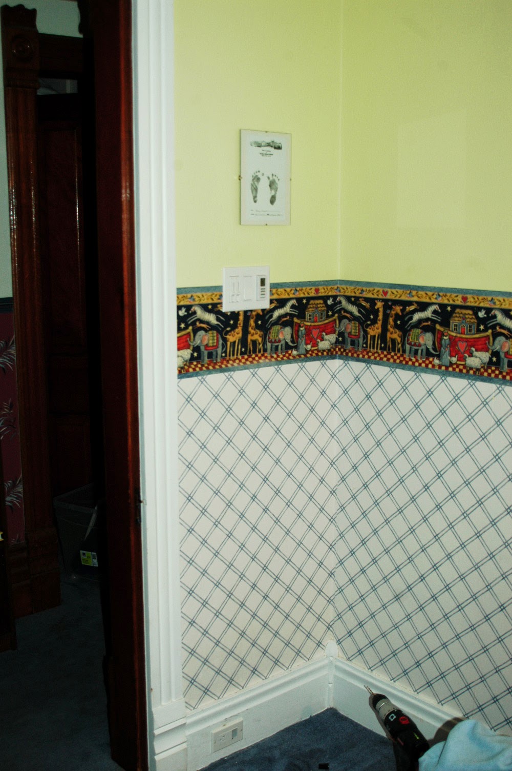
STEP 1: About ten hours into the job, after determining the best routing for the three wires entering this two gang switch box. One wire is from the source, the others will feed two ceiling lights in the sunroom just outside the main door. These wires travel up and down the inside cavity of the wall on the right.


STEP 2: Sprayfoaming around the receptacle box. These houses have no vapour barrier and no air barrier behind the brick wall, relying entirely on a continuous and unbroken plaster on lath wall to stop airflow. Holes that break through the plaster must be sprayfoamed or sealed in some fashion. While this hole was open, quite a cold draft came in especially when the outside temp fell to -22 C.


STEP 3: After the sprayfoam has cured, it is cut back to just beneath the wall surface, about 1/4 inch deep. There is no need to apply a piece of drywall over the sprayfoamed area, just plaster directly onto it.


STEP 4: Two metal plates are added to protect the cables from any misdirected drywall screw, now or in the future. The holes that the cables are run through are only a quarter inch deep in the wood strapping.


STEP 5: A small section of drywall is cut out and fixed in place with four drywall screws. I never bother taping joints in repairs this size, as multiple layers of drywall compound will be added, and the length of the joints is so short.


STEP 6: The first coat of drywall compound is added, not too thick, to keep drying time down. There will probably be  close to ten more applications with sanding between to achieve a perfect finish. The compound added close to the doorframe is where the old single switch was located (see previous post).


STEP 7: After the fourth or fifth layer of drywall compound is added, things are looking better.


STEP 8: I think it was about 9 layers of drywall compound before the wall was to my liking. Plaster walls are far from flat, so it is a challenge to match the very slight undulations of the walls, and each time  you sand, you remove too much compound from some areas, and not enough from others.


STEP 9: The Lutron switches and switchplate cover installed. Look, no screws! And a magnificently contoured wall!


STEP 10: No photograph for step 10, clean up, and crack open a cold beer!

Tuesday, December 14, 2010

Foyer Switches and Lighting

With the opportunity accorded by being forced to pull up the floor in Rudi's bedroom to address the heating conduit problem, I recognized that this gave me the perfect opportunity to address the layout, planning, and installation of all the wiring for the foyer, front living room, and the sunroom. The opening in the wall between the foyer and living room up which the heating stack rises also gives opportunity to run wiring from switches in the foyer and living room to lights in both of these rooms, as well as lights in the sunroom


LEFT: The opening in the foyer wall was original to the construction of the house. Three switches located here controlled the upstairs landing light, foyer light, and front living room light.

RIGHT: New three gang box test fit. This will now house a switch for the foyer light, a switched duplex in the foyer, as well as the Lutron Radio RA 2 master control.


ABOVE: This switch was initially added in the 'twenties or so when the sunroom was built. It is almost 6' high, and located directly against the door trim. I will relocate a two gang box down and to the right (note the rough markings) which will switch one sunroom light, and the outdoor sunroom lights.

Friday, October 1, 2010

Illegal Wiring? Fancy That!

The newly installed octagonal box, seen through the basement floor. A two by four support was cut to length, and installed using a 'custom bent' hurricane bracket (the small metal tab at the end of the support). This box will now support my weight, so a ceiling fan or pendant lamp shouldn't be a problem. The cable is the original wire to the pancake box... note how it lies on top of the attic floor joist, a definite code violation!


This photo looks the other way, with the floorboard now pulled up. The original cable was laid over the joists, a fantastic idea if someone decided to drive a nail to keep the loose floorboard down, and cause a short circuit or electrocute themselves.


Looking down the run of the pulled up floorboard, to a lovely tangled mess of wiring at the end!


Wow! that's three wires laid directly over the joist... and a connection between live wires made outside a junction box! A wonderful smattering of Electrical Code violations!


A photo of the pancake box I removed (see previous post) and the three dinky little screws holding it to the lath. Over time either the screws or the lath would have given way if a heavier lamp had been installed on this box.

Tuesday, September 28, 2010

Doing It Right!

From the 'how not to properly re-wire an historic home' comes the following example:

On the left the landing light was installed with a flat pancake style round box, which has been screwed into the lath after the plaster was broken away to allow it to fit. These boxes are so small that you can't legally make a junction in them, meaning they always have to be at the end of a wire run. The two half inch #4 screws wouldn't support much fixture weight either. Avoid using these if at all possible.

On the right I have removed the pancake box, cut through the lath, and installed a standard ocagon box which is screwed into a 2 x 4 brace spanning the joists above. There is more space in this box, and it can support a lot more weight as it is now screwed into a structural support brace, rather than just the lath.


. . . . . The Wrong Way . . . . . . . . . . . . . The Right Way . . . . .

Wednesday, September 15, 2010

Do's And Dont's - Some Thoughts

Thinking about re-wiring your historic home? What follows are some of my thoughts on the things one should do, or not do, when undertaking such a project, whether it be done by the homeowner, or by hiring a professional electrician.

DO keep things consistent, in terms of location of outlets, switches, and other electrical boxes. Some may question why I installed all of the receptacle outlets horizontally in the baseboard. The houses original dozen or so outlets were installed this way, so I continued with the rest the same way.

DON'T just do the minimum that the code requires. If you are dropping hundreds of hours and thousands of dollars on the project, you might as well do the job right. Put in sufficient (or more than sufficient) lights and outlets, and don't let anyone tell you "that's all you need to do". Once you close everything up, repair all the openings, and put your tools away, you don't want to come back to the job because you left something useful out.

DO make certain you have the skills and experience necessary to undertake the job yourself, or hire a licenced electrician with the same attributes. Many obstacles I encountered, and issues I resolved are things that simply took a bit of thought and imagination to deal with. Re-wiring these old houses is absolutely nothing like wiring a new framed house (trust me, I have done work on both).

DON'T exclude things because you think (or someone tells you) it can't be done. With time, patience, and yes money, anything reasonable can be accomplished. How much extra work was it really to wire in not just one, but three staircase lights in our front foyer? I now have a chandalier, landing light, and hall lights operated via three-way switches at both the bottom and top of the stairscase.
ToolBarn
1000Bulbs.com
BuildDirect: Free Samples with New Lower Shipping Rates