Sunday, January 30, 2011

Lutron Cover Plates


Lutron colour co-ordinated switches installed in electrical box. Lutron offers their products in close to 50 different colours to complement any decor. I chose 'terra-cotta' as it looked best for duplexes mounted in the baseboards, and though quite rich, was also a neutral enough colour choice.


The base plate of the cover plate is installed. The openings allow fine adjustements to be made in levelling the switches without having to take this base plate off.


The top plate simply clicks into postion on the base plate, hiding all of the mounting screws, leaving a gorgeous finished appearance, very neat and tidy.

Thursday, January 27, 2011

The Ten Step Program To Fixing Holes In Walls!


STEP 1: About ten hours into the job, after determining the best routing for the three wires entering this two gang switch box. One wire is from the source, the others will feed two ceiling lights in the sunroom just outside the main door. These wires travel up and down the inside cavity of the wall on the right.


STEP 2: Sprayfoaming around the receptacle box. These houses have no vapour barrier and no air barrier behind the brick wall, relying entirely on a continuous and unbroken plaster on lath wall to stop airflow. Holes that break through the plaster must be sprayfoamed or sealed in some fashion. While this hole was open, quite a cold draft came in especially when the outside temp fell to -22 C.


STEP 3: After the sprayfoam has cured, it is cut back to just beneath the wall surface, about 1/4 inch deep. There is no need to apply a piece of drywall over the sprayfoamed area, just plaster directly onto it.


STEP 4: Two metal plates are added to protect the cables from any misdirected drywall screw, now or in the future. The holes that the cables are run through are only a quarter inch deep in the wood strapping.


STEP 5: A small section of drywall is cut out and fixed in place with four drywall screws. I never bother taping joints in repairs this size, as multiple layers of drywall compound will be added, and the length of the joints is so short.


STEP 6: The first coat of drywall compound is added, not too thick, to keep drying time down. There will probably be  close to ten more applications with sanding between to achieve a perfect finish. The compound added close to the doorframe is where the old single switch was located (see previous post).


STEP 7: After the fourth or fifth layer of drywall compound is added, things are looking better.


STEP 8: I think it was about 9 layers of drywall compound before the wall was to my liking. Plaster walls are far from flat, so it is a challenge to match the very slight undulations of the walls, and each time  you sand, you remove too much compound from some areas, and not enough from others.


STEP 9: The Lutron switches and switchplate cover installed. Look, no screws! And a magnificently contoured wall!


STEP 10: No photograph for step 10, clean up, and crack open a cold beer!

Tuesday, December 14, 2010

Foyer Switches and Lighting

With the opportunity accorded by being forced to pull up the floor in Rudi's bedroom to address the heating conduit problem, I recognized that this gave me the perfect opportunity to address the layout, planning, and installation of all the wiring for the foyer, front living room, and the sunroom. The opening in the wall between the foyer and living room up which the heating stack rises also gives opportunity to run wiring from switches in the foyer and living room to lights in both of these rooms, as well as lights in the sunroom


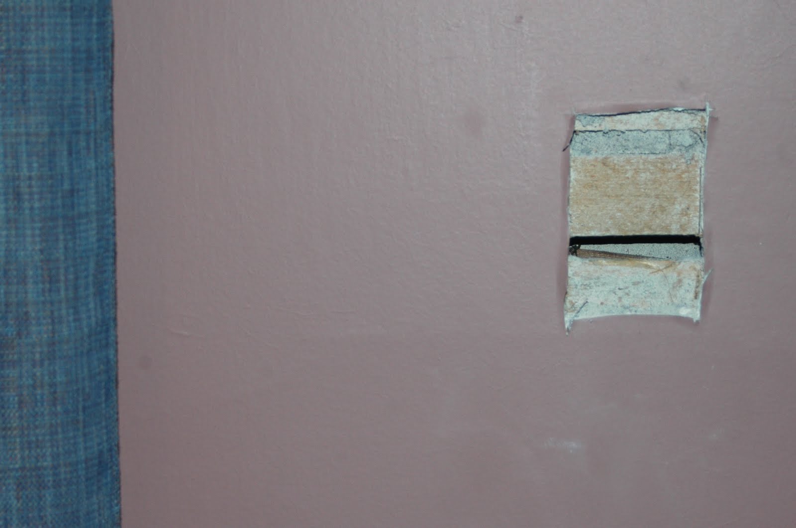
LEFT: The opening in the foyer wall was original to the construction of the house. Three switches located here controlled the upstairs landing light, foyer light, and front living room light.

RIGHT: New three gang box test fit. This will now house a switch for the foyer light, a switched duplex in the foyer, as well as the Lutron Radio RA 2 master control.


ABOVE: This switch was initially added in the 'twenties or so when the sunroom was built. It is almost 6' high, and located directly against the door trim. I will relocate a two gang box down and to the right (note the rough markings) which will switch one sunroom light, and the outdoor sunroom lights.

Friday, October 1, 2010

Illegal Wiring? Fancy That!

The newly installed octagonal box, seen through the basement floor. A two by four support was cut to length, and installed using a 'custom bent' hurricane bracket (the small metal tab at the end of the support). This box will now support my weight, so a ceiling fan or pendant lamp shouldn't be a problem. The cable is the original wire to the pancake box... note how it lies on top of the attic floor joist, a definite code violation!


This photo looks the other way, with the floorboard now pulled up. The original cable was laid over the joists, a fantastic idea if someone decided to drive a nail to keep the loose floorboard down, and cause a short circuit or electrocute themselves.


Looking down the run of the pulled up floorboard, to a lovely tangled mess of wiring at the end!


Wow! that's three wires laid directly over the joist... and a connection between live wires made outside a junction box! A wonderful smattering of Electrical Code violations!


A photo of the pancake box I removed (see previous post) and the three dinky little screws holding it to the lath. Over time either the screws or the lath would have given way if a heavier lamp had been installed on this box.

Tuesday, September 28, 2010

Doing It Right!

From the 'how not to properly re-wire an historic home' comes the following example:

On the left the landing light was installed with a flat pancake style round box, which has been screwed into the lath after the plaster was broken away to allow it to fit. These boxes are so small that you can't legally make a junction in them, meaning they always have to be at the end of a wire run. The two half inch #4 screws wouldn't support much fixture weight either. Avoid using these if at all possible.

On the right I have removed the pancake box, cut through the lath, and installed a standard ocagon box which is screwed into a 2 x 4 brace spanning the joists above. There is more space in this box, and it can support a lot more weight as it is now screwed into a structural support brace, rather than just the lath.


. . . . . The Wrong Way . . . . . . . . . . . . . The Right Way . . . . .

Wednesday, September 15, 2010

Do's And Dont's - Some Thoughts

Thinking about re-wiring your historic home? What follows are some of my thoughts on the things one should do, or not do, when undertaking such a project, whether it be done by the homeowner, or by hiring a professional electrician.

DO keep things consistent, in terms of location of outlets, switches, and other electrical boxes. Some may question why I installed all of the receptacle outlets horizontally in the baseboard. The houses original dozen or so outlets were installed this way, so I continued with the rest the same way.

DON'T just do the minimum that the code requires. If you are dropping hundreds of hours and thousands of dollars on the project, you might as well do the job right. Put in sufficient (or more than sufficient) lights and outlets, and don't let anyone tell you "that's all you need to do". Once you close everything up, repair all the openings, and put your tools away, you don't want to come back to the job because you left something useful out.

DO make certain you have the skills and experience necessary to undertake the job yourself, or hire a licenced electrician with the same attributes. Many obstacles I encountered, and issues I resolved are things that simply took a bit of thought and imagination to deal with. Re-wiring these old houses is absolutely nothing like wiring a new framed house (trust me, I have done work on both).

DON'T exclude things because you think (or someone tells you) it can't be done. With time, patience, and yes money, anything reasonable can be accomplished. How much extra work was it really to wire in not just one, but three staircase lights in our front foyer? I now have a chandalier, landing light, and hall lights operated via three-way switches at both the bottom and top of the stairscase.

Sunday, September 12, 2010

Great Fishing Tales

I imagine I could cut the time it takes to wire the house by stripping the plaster and lath down completely, or making large holes in locations I want to run wire, but since the plaster has stood up well for a hundred and twenty-five years, and the purist in me doesn't want studded and drywalled walls, or lots of repair work to do, so the only thing to do to run wires is the painstaking process known as fishing.

Fishing essentially means routing wire through existing walls generally from unfinished areas, to the boxes that are to be supplied by said wires, all while making the minimal number of openings as possible. Generally it is easy enough to fish a wire down from the attic to a duplex outlet at the bottom of the wall, however there are times that obstructions prevent succesful fishing, and  a small opening must be made to aid in routing the wire.

Determining the correct location is the art, as you have to carefully determine the distance from where you are fishing that the obstruction occurs. Usually measuring the length of the fished wire (accounting for flex), and also knocking on the wall listening for more 'solid' sounds than 'hollow' will get you close, as the following examples illustrate.

I fished down this exterior wall about 5 feet, knocking up and down revealed a solid area, which I opened up exposing the lath.


After cutting out the lath, the cause of the obstruction was evident. The small wooden key between the courses of brick had bridged to the plaster, blocking my wire.


After cleaning the plaster out, I fished the wire into the opening, then continued it down the wall to the outlet in the baseboard. A small wire hook, penlight, and piece of mirror are very useful tools when fishing.

Friday, August 6, 2010

Keeping Things Tidy

On entering the main panel, sufficient branch conductor wire must be left in the box in case any rewiring changes are made. Generally just enough wire to run straight to the neutral or ground bus and the hot to the appropriate breaker is not considered sufficient.

I like to leave about 18 inches or so, then simply run the wire up or down anto a long U shape, and then to the bus or breaker, as seen in the picture here. Looks really sweet in my opinion.


Tuesday, February 16, 2010

Switched GFCI Outlets!

This is something you will rarely see done, but is a great idea. All outdoor receptacles must be ground fault protected, either with a GFCI Receptacle, or GFCI breaker protecting the circuit from the panel.

The typical cost of a GFCI outlet is about $15, and it can protect other outlets as you want further along the circuit. A GFCI breaker protects all outlets on its circuit, yet costs over $100. Obviously the best way is to run a GFCI outlet first in the circuit to protect all other outlets wired beyond it. 

So the other problems are that GFCI's are the ugly decora style, which I refuse to mount on the outside of this fine edifice, and my preference for having outdoor receptacles switched, for safety and to prevent neighbors charging their plug-in hybrids at our house when we aren't around! But GFCI outlets can't be switched on or off, as the outlet would have to be reset each time power is returned.

My solution? A GFCI is wired first in the circuit off the panel, located 'outdoors' underneath the front porch, hidden away from view. From there wire is run to this switch, from which all 3 outdoor outlets will be controlled, one switch for a single driveway outlet, the other switch for two garden side outlets.


Monday, February 15, 2010

Cable Holders

This photo shows the full cable run to the attic, in the short space in the basement where they run under the floor joists from the panel to where they turn and run up the inside of the foyer wall. I found these red plastic cable holders, knowing they would come in handy wiring the attic, and for other locations, such as between two main air ducts here, where I didn't have enough room to drill holes through the joists to accommodate the cable. Each holder can carry four 2-wire and two 3-wire cables.


Saturday, January 23, 2010

Three Way Action

This is a photo of the newly installed 3 box gang at the foot of the main staircase. Conveniently, the depth from the finish plaster wall to the first layer of brick beneath was 2-1/2 inches, exactly the depth of the boxes. These are the 'old style' boxes with four knockout openings (two back and one each top and bottom) as opposed to the newer boxes with integrated clamps entering the top and bottom near the back.

This box gang was a breeze to install after fishing the three 3-wire cables down from the attic, along the floor joists in the basement, then up the exterior wall between the inside brick layer and the lath and plaster. Instead of using metal knockout clamps with screws, I used these newer plastic one-way spring loaded clamps, which permit the cable to be slid into the box, but not back out.

After the box was installed, I sprayed low expansion foam around it to lock it in place and seal the opening from drafts. I imagine to meet the electrical code I will have to drill and 'tapcon' the gang in place, but that is really unnecessary as the cured foam holds it in place as if it were fixed in concrete.

Another sweet thing is that the switchplate covers the entire opening, so I won't even have to fix the wall whatsoever! And the three 3-wire cables? I will have a chandelier hanging over the staircase, a ceiling light on the landing, as well as second floor hall lights controlled from both the top and bottom of the stairs (and the other end of the hall in the case of the hall lights).


Tuesday, November 24, 2009

One Word - SHIT!

I don't like messing up, and thankfully, I don't do it often. But I admit it when I do, and I don't try to blame anything else for my screw up. Here is a perfect example: In dropping the wiring for the second floor from the attic, I have to drill holes blind, which when done correctly will go into the enclosed wall cavity so the wire can be fed down to the switch or outlet served. Bear in mind that this cavity is about an inch wide on outside walls, and there are only vague indicators as to where exactly the correct point to go drilling is. So here I messed up, as is plainly obvious. What I thought would be a nice hole into the space between the plaster/lath and the brick wall, turned out to be a nice hole that exited the ceiling of Rudi's bedroom and carved down six inches of finish wall! Fishing the wire down seemed way too easy, so after I got about 10' down, I went to check, only to find the wire hanging in the room, instead of hidden in the wall. Well, nothing a bit of plaster compound and paint won't fix.


Monday, November 23, 2009

Power Arrives at The Attic

Six branch circuits direct from the panel, and three '3-wire' cables for multi-switch lighting arriving at the attic floor. It was fun locating the top of the wall I had to drill blind into, as you will notice the lath strips are continuous, and the plaster is, almost... The wall was located directly under the area that the plaster 'keys' thinned out and disappeared, as when plastered, the keys could not be pushed up through the lath where a wall was located. If you enlarge the photograph, you can see the way the keys disappear where I have drilled down into the wall to drop the wires.


Sunday, November 22, 2009

Vintage Style Boxes

Recently I happened upon one of the neatest electrical boxes for performing retrofit wiring in an older home. Because some of the original wiring had electrical duplex receptacles located horizontally in the baseboard, I decided it would be best to continue locating additional receptacles in the baseboard also.

The problem is that most modern electrical boxes have the openings for wires to enter from the bottom or top end of the box, which makes it extremely difficult to mount the wired box 'blind' (that is fish the wires from the back, out throught the precisely cut out box opening, then into the box, which is then pushed back into the opening).

You will notice that the box pictured has back openings, which permit the wires to be run directly into the back of the box, as opposed to the top or bottom ends, which make installing the wired box a breeze!

I found these at both TimbrMart and Home Hardware, they cost around $3 each, much more expensive than the $1.19 or so for a regular box, but way way easier to install! Check an upcoming post for comparison pictures of installation of these versus standard boxes.


Wednesday, April 1, 2009

Where Is The Tapestry When You Need It!

After much deliberation of the best and least material consuming method of running electrical cable to the attic, I finally decided to go up the front foyer wall. I had thought of running a large cable up one of the inside kitchen walls and serving a sub panel, but with all the capacity I have in the main panel that would have been a waste. I also thought of running all cables up the same wall, but I couldn't get around the fact it would take almost 500 feet of wire just to get access to the attic. I have no idea why I hadn't thought of the foyer wall earlier, as it is located just above the breaker panel, and will save about 300' of cable, and probably 10 hours worth of work. The other reason the Foyer works so well is I will be running three sets of 3-way fixtures (Lights that can be operated at the foot or the top of a staircase) and they consume ridiculous amounts of 3 wire cable, especially if you have to run it from a switch, down a wall, across the basement, up 20' to the attic, along the floor to the fixture, and then from the fixture to the light switch controlling from the top of the stairs. The first photo is looking up the staircase, showing the three openings required to run the cables from the basement to the attic. Second is a closer look at one of the openings, required as i had to negotiate the cables past a cross brace mounted perpendicular to the wall studs. The third photo is the opening that allowed me access to make the holes necessary to run the cables through the floor.
ToolBarn
1000Bulbs.com
BuildDirect: Free Samples with New Lower Shipping Rates